
Glare in Reproduction
Three HDR Techniques
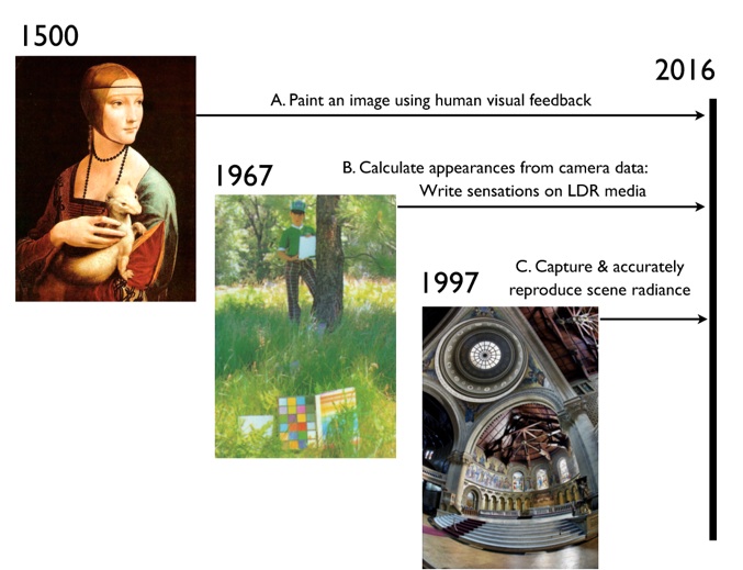
Painters have reproduced High Dynamic Range (HDR) scenes for 5 centuries; photographers have used multiple exposures for 165 years; scientists have used electronic imaging modifications of range for 50 years. This paper reviews the history of the different rendition techniques. Some techniques use trial and error to find the best rendition. Others use psychophysical models of human vision, or physical models of color cameras. All techniques use the partnership of the physics of light, and the psychophysics of human vision. [1]
All three techniques described in this review can make beautiful HDR images. All successful examples require psychophysical transformations, a kind of visual impedance match between the display and the human vision. All successful HDR images are the result of the partnership of the reproduction technology and the observer’s spatial imaging mechanisms.
-
[1] McCann J., “Rendition techniques for HDR scenes in painting, photography, and electronic imaging” in Proc. ICIP Conference, IEEE, Phoenix, Az., 874-878, 2016.
Painting
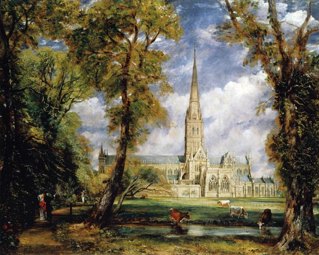
For centuries, artists have created paintings that reproduce the appearance of HDR scenes in Low-Dynamic-Range (LDR) reflective media. Early Chinese scroll paintings reproduced people in uniform illumination on an unpainted scroll background. Early Renaissance painters reproduced their subjects in uniform illumination. Da Vinci, Caravaggio, Rembrandt, van Honthorst, Constable, and Martin, synthesized HDR scenes in Low-Dynamic-Range (LDR) media - oil on canvas.[2, 3 Ch4] The painters technique for reproducing HDR scenes used the approach of matching the appearance of the scene. The painter used his Human Visual System (HVS) to render the scene as it appeared to him. There was no attempt to reproduce scene radiances. Painters matched appearances. Skilled painters learned how to spatially render the scene to create HDR appearances in LDR media. The painter’s HVS was the most important signal processing component.(Fig2.)
Painters’ Technique
In the first HDR technique, painting is usually thought of as an art, rather than a scientific process. The painter’s ground truth is the appearance of the image. The theory is all psychophysics. The painter’s HVS does the spatial transformation of the HDR radiances to generate the sensations. The reflectance gamut of paints is so small that the painter cannot reproduce the scene’s radiances. The painter has to learn how to synthesize the spatial patterns that create HDR sensations. The painter’s HVS provided the feedback needed to generate spatial patterns that have very similar sensations from vastly different radiances.
-
[2] McCann J. ( 2007 ) “Art, Science, and Appearance in HDR Images”, J Soc Info Display , 15 ( 9 ), 709 – 19 .
-
<http://www.mccannimaging.com/Lightness/HDR_Papers_files/07HDR1Hist.pdf>
-
-
[3] McCann J. and A. Rizzi, (2012) The Art and Science of HDR Imaging, Wiley, Chichester. ISBN: 978-0-470-66622-7
Photography
Multiple exposures of silver halide photographs are found in the early 1850‘s. Edouard Baldus used 10 negatives to make the above print. The emulsions of that era had limited dynamic range (Fig.3). Taking a series of photographs with different exposures recorded different light ranges of the scene. Combining these exposures resulted in images of the entire scene’s range. There were many examples of AgX multiple exposure techniques until the 1930’s, when emulsion technology advanced to being able to capture the range of light on the cameras’ film planes. [3; Ch 5] Ansel Adam’s zone system, and his remarkable photography show that standard negatives are able to capture all the visual information in the natural image. [4]
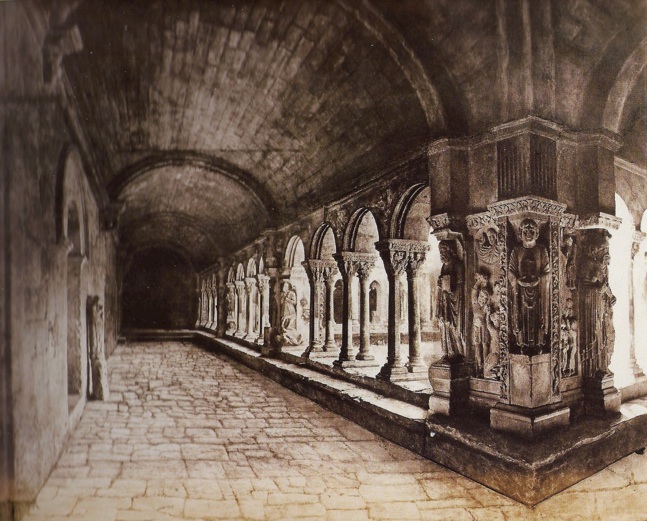
Just as with painting, the photographer’s HVS was the most important signal processing component. Multiple exposures capture different spatial records of the HDR scene. In 1853, Baldus found a way to combine the 10 different negative exposures to generate a print that reproduced the entire dynamic range of the Baldus’s Cloisters at Arles. As well today, there are many examples of digitally fused multiple exposures that are made with human trial and error. By combining the highest contrast portion of multiple exposures with desirable LUTs, one can create merged images that conform to the rendering artist’s aesthetic intent. Regardless of the media (oil, AgX, or Jpeg images) this first approach is built around the mechanisms of the artist’s HVS. Whether using paint, film, or LUTs, image manipulations based on observer preference are all examples of the Painter’s Technique.
-
[4] McCann, J., (2010) “The Ansel Adams zone system: HDR capture and range compression by chemical processing”.Proc. SPIE 7527, Human Vision and Electronic Imaging XV, 75270S; doi: 10.1117/12.844972
-
http://mccannimaging.com/Retinex/Talks_files/Zones7527-28.pdf
-
-
-
Electronic Imaging
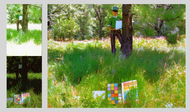
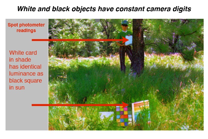
“John at Yosemite”, 1981, (Fig. 4) is an example of an HDR image taken in sun and shade. The photometer reading from the white card in John’s hand in shade was equal to that from the black paper in the ColorChecker® in sunlight. The scene was captured on color negative film, scanned and converted to scene radiances by calibration. These scene radiances were used as input to separate RGB Frankle & McCann Retinex calculations.[5] The calculated sensations were scaled by standard tone scale and color enhancement algorithms to match the expected color space to be printed on film. This algorithm realized that calculated sensations are in the middle of the image processing chain.[3 Ch7,32] [ 5 ]
Display Calculated Sensation Technique
In the second HDR approach, cameras capture scene radiances, and digital algorithms calculate sensations. It incorporated both physical and psychophysical disciplines. It used the best practices of capturing the widest range of radiances possible. It recognized that the capture process include technology-limited accuracy. It used a spatial-comparison model of vision that calculated sensations. It recognized that the vision model is in the middle of the image processing chain. The final step rendered an HVS model’s output into the colorspace of the display device. The goal is to render calculated sensation. The ground truth here is appearance matches of test areas in many different complex images. Psychophysical matching measurements were used to determine the best parameters of the model. They selected the vision model that calculated sensations most accurately. [3,Ch 7,32]
This second technique used best practices to capture the largest possible range of scene radiances recognizing the limits from glare. This technique never assumed that the captured data was an accurate record of scene radiances.
-
[5] Frankle J & McCann J (1983) Method and Apparatus of Lightness Imaging, U.S. Patent, 4384336, issued 5/17/)1983)
-
Capture and Reproduce Radiances Technique
In the third HDR approach, renditions are based on accurately reproducing light.[6,7] Here, the ground truth is whether the reproduced image has identical radiances everywhere in the image. If the HDR system does that, then the reproduction must match the scene. However, there are two problems that this technique needs to consider:
-
• First, camera makers do not want accurate, unenhanced, scene reproduction. Images with enhanced tone scale and chroma are preferred.
-
• Second, camera optics limit the range of accurate scene capture. As with all physical systems, cameras have physical limits to the critical assumptions of: reciprocity, linearity and optical glare.
Measurements of camera limitations show that reciprocity is generally good. Glare in the image on the camera’s sensor presents the most serious challenge to inverse CRF calibration. Camera responses are highly scene dependent, particularly in HDR scenes [3 Ch 10-13] [8]
See Camera Glare Spread Function
Although the reproduce radiance technique begins the process with pure physics, the output image needs addition enhancement. Calculated radiances have a limited color space. In order to fill the display device’s color space nonlinear transforms are required. SEE Standard sRGB vs. RAW format
When we test the use of HDR camera multiple exposures as a meter for measuring scene radiances, we find that optical glare limits the cameras performance. Even scenes with only 20 to 1 dynamic range (beach scene), variable glare from variable scene content has substantial effect of camera digit values. Cameras cannot compete with telephotometers as a tool for measuring scene radiance.[9]
SEE REVIEW: Glare in Computer Vision
-
[6] Debevec P. and Malik P. (1997) "Recovering High Dynamic Range Radiance Maps from Photographs", ACM SIGGRAPH’97, 369-78 .
-
[7] Reinhard E., Ward, G., Pattanaik, S., and Debevec, P., (2006) High Dynamic Range Imaging Acquisition, Display and Image-Based Lighting, Elsevier, Morgan Kaufmann, Amsterdam .
-
[8] McCann, J. J. and Rizzi, A (2007) “Camera and visual veiling glare in HDR images”, J. Soc. Information Display, vol. 15(9),
-
<http://www.mccannimaging.com/Lightness/HDR_Papers_files/07HDR2Exp.pdf>
-
[9] J. McCann,”ColorChecker at the beach: dangers of sunburn and glare” Proc. SPIE 9015, Color Imaging XIX: 90150V ( 2014); doi:10.1117/12.2045379
-
Spatial vs. Pixel-based HDR transformations
The “John at Yosemite, 1981” image provides insight into the HDR processing necessary for reproducing appearances. Both white and black objects have the same scene radiances. Scene transformations that use only one pixel in the process cannot differentiate white from black. Single pixel LUTs cannot have a high-output value for white, and a low output-value for black. Both objects have generated identical camera digits, and hence identical output values. Spatial processes, involving the entire image, are needed to render white paper with digits near max, and black paper with digits near min.
The analysis of the two electronic imaging techniques shows interesting differences.
-
• Calculation of appearance in real-life scenes requires a spatial computation involving the entire scene
-
•Accurate radiance calculation can be single pixel LUTs, or spatial transformation using data from the entire scene.
-
•Single pixels LUTS cannot calculate appearances in “John at Yosemite”; spatial processes are required.
Land and McCann’s Retinex 1971 [10] introduced spatial processing of entire scenes. It was followed by Frankle and McCann,1983[11] with a multiresolution Retinex calculation[12,13]. It was followed by pyramid processing[15] and bilateral filtering.[16] See Vonikakis review.[17]
-
-
-
[10] E. H. Land and J. J. McCann “Lightness and Retinex Theory”, J. Opt. Soc. Am. 61 1-11, 1971.
-
L&M1971.pdf
-
-
[11] J. Frankle and J. J. McCann, “Method and apparatus of lightness imaging”, US Patent, 4,384,336, Filed Aug 29, 1980; Issued May 17, 1983.
-
-
[12] J. McCann, “Lessons Learned from Mondrians Applied to Real Images and Color Gamuts”, Proc. IS&T/SID Seventh Color Imaging Conference, 1-8, 1999.
-
-
[13] J. McCann, “Black Capturing a black cat in shade: past and present of Retinex color appearance models”, Journal of Electronic Imaging, 13, 36-47, 2004.
-
[14] J. McCann, (2016) “Retinex Algorithms: Many spatial processes used to solve many different problems”, In Retinex at 50, Proc Electronic Imaging, pp. 1-10(10).
-
<http://mccannimaging.com/Retinex/Talks_files/McCann%20Proc%20RET50.pdf>
-
-
[15] P.J. Burt and E.H. Adelson. (1983) The laplacian pyramid as a compact image code. Communications, IEEE Transactions on, 31(4):532– 540,
-
-
[16] C. Tomasi and R. Manduchi. Bilateral filtering for gray and color images. In Computer Vision, 1998. Sixth International Conference, pages 839–846, Jan 1998.
-
-
[17] V. Vonikakis, and S. Winkler, A center-surround framework for spatial image processing in Retinex at 50,Proc. Electronic Imaging ,pp. 1-8(8) Society for Imaging Science and Technology
-
<http://www.ingentaconnect.com/contentone/ist/ei/2016/00002016/00000006/art00005>