Glare Spread Function (GSF) - Characterization of optical glare:
Camera Glare Spread Function
Camera Optics
Camera optics collect all light rays that fall on its front surface. Well-placed lens shades reduce light from objects outside of the sensor’s field of view.
Sowerby in his “Dictionary of Photography”[1] discusses the reflection of light in lenses as the “diversion of an appreciable portion of the incident light from its intended path”. The small percentage of light reflected from each air - glass surface is called a parasitic image. Parasitic images that are completely out of focus give rise to a general fog that limits the dynamic range of the image falling on the image plane.
The left figure below shows an illustration of a 18,619 to 1 High-Dynamic Range (HDR) display. Four identical sets of pie-shaped transparencies were mounted on a uniform lightbox. The top had a uniform 0.0 ND filter covering the circle; left had 1.0; bottom had 2,0; right had 3.0. This image is a simulation the actual luminance values measured with a light meter when all other pie segments were masked off. The simulation is necessary because of the very large dynamic range of the scene.
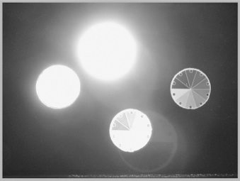
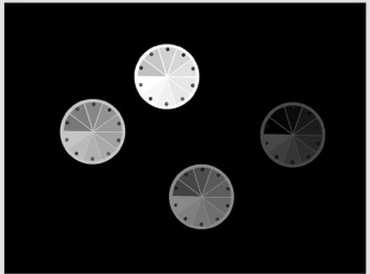
Simulation of measured luminances Actual digital photograph of the HDR display.
The right figure is an actual photograph of the scene made with a Nikon Coolpix 990. (high-quality, compact digital camera with mid-range aperture f 7.3). The exposure time was set for the best rendition of the darkest (right circle). Stray light has considerably enlarged the top circle. The photograph shows a magnified inverted in-focus parasitic image, as well as the out-of-focus fog.
The formula to count parasitic images is [2n2 - n], where n is the number of lenses[1]. The digital camera used here (Nikon Coolpix 990) has nine elements and 153 parasitic images. Kingslake [2] describes many examples of parasitic images that contribute to veiling glare.
Multiple exposures can improve the digital quantization, and thus selectively improve the camera’s performance for some parts of the scene. However, changing the length of time of the exposure has no effect on the distribution of light on the sensor. Veiling glare is the combined result of optics and scene content: together they determine the amount of glare added to each pixel. The fraction of added glare, compared to scene radiance, is constant for all exposures. Added glare determines the dynamic range on the sensor. Assertions that multiple exposures can increase a camera’s dynamic range requires unreasonable assumptions about glare-free camera optics.[3,4]
-
[1] Sowerby A ( 1956) Dictionary of Photography , 18th ed. Philosophical Library , New York , p 568
-
[2] Kingslake R ( 1992 ) Optics in Photography, SPIE Press , Bellingham .
-
[3] McCann, J. J. and Rizzi, A (2007) “Camera and visual veiling glare in HDR images”, J. Soc. Information Display, vol. 15(9).
-
<http://www.mccannimaging.com/Lightness/HDR_Papers_files/07HDR2Exp.pdf>
-
[4] McCann J. and A. Rizzi, The Art and Science of HDR Imaging, Ch 11, Wiley, Chichester, (2012).
-
ISBN: 978-0-470-66622-7
ISO Glare Standard
The ISO Standard for Glare (9358:1994) [5] provides a standard to compare different lenses and apertures. It uses a test target that has light sources outside the camera’s field of view. It states that it is possible to calculate the effects of glare given the lens Glare Spread Function (GSF), and array of the scene radiances.
Some HDR algorithms attempt to reverse the process, namely correct for glare [6,7]. However, these papers use visual inspection of algorithm outputs as the verification of concept. They do not compare actual scene radiances with calculated values.
The glare spread functions of commercial lenses fall off very rapidly with distance to a very small value. We might think that such small glare values cannot affect distant pixels. However, there are millions of pixels that contribute glare to all other pixels. The light at each pixel is the sum of scene luminance plus scattered light from all other pixels. The sum of a very large number of small contributions is a large number. Sorting out these millions of scene-dependent contributions would be required to correct precisely for glare in physical units. The ISO 9358:1994 Standard [5] states unequivocally that: “the reverse (deriving radiance from camera response) calculation is not possible. ”
-
------
-
[5] ISO Standard 9358 - Optics and Optical Instruments, Veiling Glare of Image Forming Systems: Definitions and Methods of Measurement , ISO 9358 : 1994.
-
[6] Talvala, E, Andrew Adams,A.Mark Horowitz, M.& Levoy,M.(2007) “Veiling Glare in High Dynamic Range Imaging”, SIGGRAPH: ACM Transactions on Graphics, Vol. 26, No. 3, Article 37, Publication date: July 2007.
-
[7] Raskar,R., A Agrawal,A., C Wilson,C., A Veeraraghavan, (2008) “Glare Aware Photography: 4D Ray Sampling for Reducing Glare Effects of Camera Lenses”,SIGGRAPH 2008
