Glare in Photography
The Role of Scene Content
The first step in vision and reproduction is imaging. Optical veiling glare limits the dynamic range of the image on the sensor.
Fig.1 (top left) is a Jpeg photograph of a Low-Dynamic-Range (LDR) scene using a Canon D60 camera with Canon EF 50 mm F/1.8 II primary lens having only five optical elements (so as to minimize glare). The left side of the image is a ColorChecker® reflection target; the right side has an Aladdin® LED lightbox turned off. The center of the lightbox with all LEDs off is 15.6 cd/m2. Fig.1 (top right) is taken with the same exposure with the lightbox on. The lightbox was placed several feet in front of the ColorChecker, with an opaque light shield behind it. None of the light from the lightbox fell on the chair, the wall and the ColorChecker.
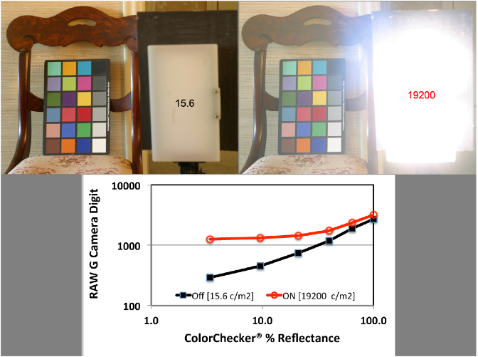
Fig. 1(bottom) plots the RAW G camera digits (log scale) extracted by DCRAW for the six achromatic squares.
The luminance at the lightbox center (turned on) was 19,200 cd/m2. The bright lightbox has increased the scenes range by three log units.
The Jpeg photographs provide an illustration of the effects of glare, but they also introduce nonlinear transformations of sensor response, namely tone scale and color enhancement. In order to measure the light falling on the camera’s sensor we extract data from RAW images. Fig. 1 (bottom) plots LibRAW digits extracted from Green RAW images made with the same camera.[1] By using RAW we remove most of the signal processing in the cameras firmware, and get to see the spatial effects of glare on the camera sensor. The data plotted in black in Fig.1 (bottom) shows the RAW G camera digits for the 6 achromatic squares in the ColorChecker® with the lightbox off.
Turning the lightbox on added light to a different part of the scene. The lightbox was positioned so that its light did not increase the ColorChecker’s radiances. The increase in the scene’s dynamic range added glare to the image of the ColorChecker® on the sensor, as seen in the red curve in Fig. 1 bottom). The camera digits from identical scene radiances have much higher values. The camera’s optical glare added only 20% to the RAW G digits for the White square. It added 90% to the middle-gray (4th) square, and 334% to the Black. The Black square with glare is slightly higher digit than the third gray square with the lightbox off. The black square digit changed from digit 290 to 1259 with glare.
Fig. 1 demonstrates that when a very bright object is added to an LDR scene, it can alter the camera’s response to the entire LDR portion of the HDR scene. The lightbox added 3 log units of range.
Glare in Low-Dynamic-Range Scenes
While dynamic range is an important variable in glare, it is not the only factor. Every pixel contributes glare to every other pixel. The amount of glare added to a pixel depends on the intensity of the contributing pixel and its distance. The amount of glare decreases with distance.
Optical glare responds to the content of the entire scene.[2] Photographs of stars at night without terrestrial objects have very low glare. Most of the pixels make very low glare contributions. The counter-example is Low-Dynamic- Range(LDR) scenes with very high-average luminance. If the scene has maximal luminance in almost every pixel, then every pixel makes a large glare contribution. Such LDR scenes are modified by glare. Figure 2 shows a ColorChecker® on a beach. It demonstrate the strong distortions of scene radiance by the camera’s imaging system.[3]
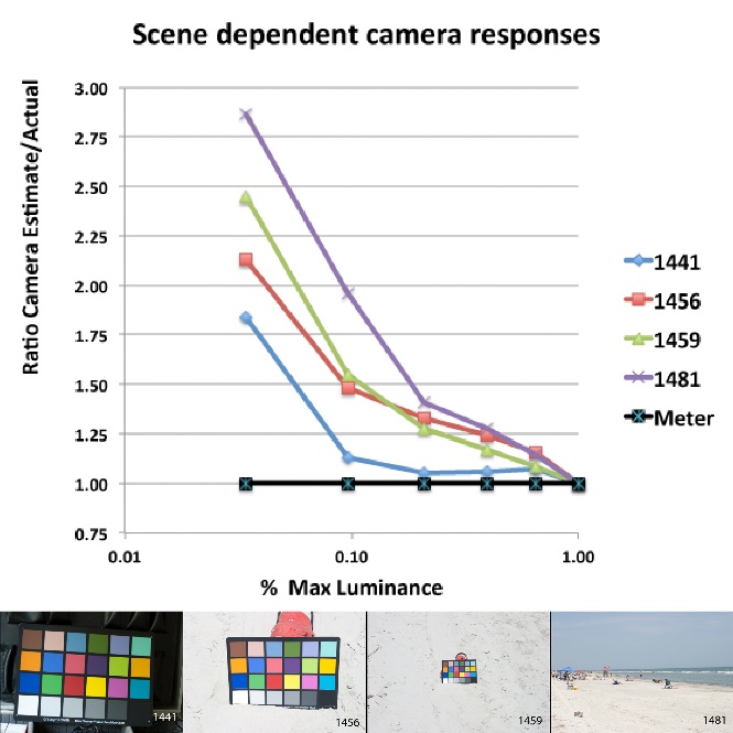
Fig2 (bottom) Four photographs containing a ColorChecker® . Each photograph has an increasing amount of high luminance pixels that vary scene content.
Glare is a complex spatial transformation of the scenes radiances that responds to the scene’s content.[2] Glare’s influence can be calculated by the convolution of the camera’s Glare Spread Function with the radiance at each pixel.
-----
-
[1] J. McCann, and V. Vonikakis, "Accurate Information vs. Looks Good: Scientific vs. Preferred Rendering", Proc.IS&T, Color in Graphics, Imaging, and Vision; Amsterdam 6, 231-238 (2012). <http://mccannimaging.com/Retinex/Talks_files/12CGIVf.pdf>
-
[2] McCann, J., and Vonikakis, V., Bonanomi, C. and Rizzi, A. (2013) "Chromaticity limits in color constancy calculations", Proc. IS&T/SID Color Imaging Conference, 21, 52-60. <http://mccannimaging.com/Retinex/Talks_files/13CIC21.pdf>
-
[3] J. McCann,”ColorChecker at the beach: dangers of sunburn and glare” Proc. SPIE 9015, Color Imaging XIX: Displaying, Processing, Hardcopy, and Applications, 90150V ( 2014);
-
doi:10.1117/12.2045379
